| Support |
|
Please support the StampDock effort.

|
| Sponsors |
|
| Recommodations |
|
| Forums |
Stampdock forum
|
| Ads |
|
|
| Ads |

|
|
|
About:
This is a demonstration project of the Stampdock software.
("StampDock" is software that offers services to parallax "BASIC Stamps")
This project is a "javelin stamp" based universal remote control with some extras.
As it is able to show the signal it sends and receives and it can store the infrared
codes it learned on the harddisk of a PC.
All you need besides the stamp, an IR led and the receiver module is a 10Mhz oscillator can
and a CMOS 4040 counter chip.
So if you are studying infrared remotes, this might be usefull too you.
You can download the complete project from this page.
The archive contains a "Javelin stamp" program that learns and sends IR codes.
The stampdock windows/mac/linux software which acts as the display/gui/storage of the "javelin stamp".
(note that the archive also contains "basic stamp" software that tries to do the same as the "javelin stamp"
version, but it looks like the "basic stamp" is not fast enough to capture small pulses. So that
version was only added for reference .. it looks like you can't actually use it as a remote control.)
|
|
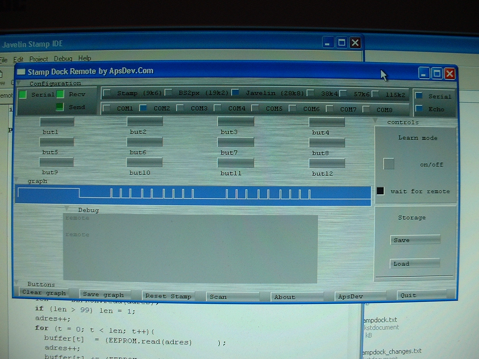
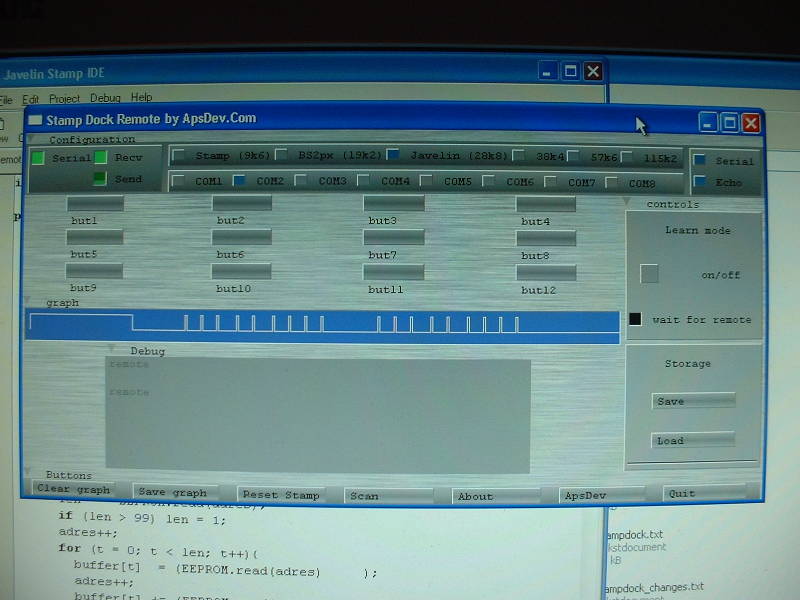
GUI:
[ click to enlarge ] |
This is the GUI of the system in action.
Note that if you select the "learn" mode, then the system will wait for you to click on a button.
If you click a button the "wait for remote" LED will light up untill the system receives a sequence
from a remote control. If you unselect the "learn" mode and select the same button then the system
will send out the received IR code.
Also it will show a graph that represents the IR pulses of the remote control.
With the load and save buttons you can transfer the learned codes to the harddisk of a PC.
|
|
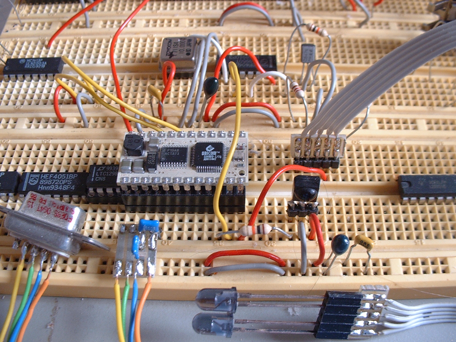
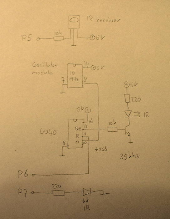
Circuit:

[ click to enlarge ]
This is a picture of the hardware used to test.
Note that there are 2 infrared LEDs, one LED is fed by a 4040 counter chip .. the other
one directly by the "Javelin stamp". But the stamp doesn't seem to be able to generate the
correct frequencies.
The circuit uses a crystal oscillator to generate 10Mhz, which is divided by a 4040 counter chip
to 39Khz. A BC547 transistor amplifies the signal to drive the IR LED.
The "Javelin stamp" controls the 4040 counter chip by making its "reset" pin high or low.
Which means that at the exact moment the 4040 get the signal to generate a signal the pulse
is there. Also because of the crystal oscillator there are no critical R's or C's that need
to be tuned to get the right frequency .. and the component count is fairly low.
|
|
|
Pictures:
[ click to enlarge ] |
Circuit diagram in more detail.
|
|
[ advertisements ]
|
|
News:
|
|
Downloads:
Latest version:
Mirror1 8-aug-10 Download V1.0 6MB Stampdock remote.
Older versions:
Mirror1 8-aug-10 Download V1.0 6MB Stampdock remote.
|
|
Feedback:
StampDock Remote
Report a bug
|
|
Copyright 2008-2010 by Arend-Paul Spijkerman
|
|
|