| Support |
|
Please support the StampDock effort.

|
| Sponsors |
|
| Recommodations |
|
| Forums |
Stampdock forum
|
| Ads |
|
|
| Ads |

|
|
|
About:
This is a demonstration project of the Stampdock software.
("StampDock" is software that offers services to parallax "BASIC Stamps")
This project is a simple radio made with a I2C car radio tuner module.
The tuner is build around two philips (now NXP) chips a TEA6810V and TEA6825T.
It is connected with the I2C bus to data pin 0 and data pin 1 or a "Basic stamp" 2P.
But in theory you can use other "basic stamps" or a "javelin stamp" if you provide
some I2C "bit bang" functions.
Right now the "basic stamp" program only supports the TEA6810/TEA6811 or TEA6823/TEA6825 chips.
You can find FM tuner modules with modern equivalents of these chips on electronics sites, but
the I2C commands or those are a little different. So with a little work, it can probably be
made working with these modern modules.
You can download the complete project from this page.
The archive contains a "Basic stamp" program that acts as the radio control.
The radio windows/mac/linux software which acts as the display/gui/storage of the "basic stamp".
|
|
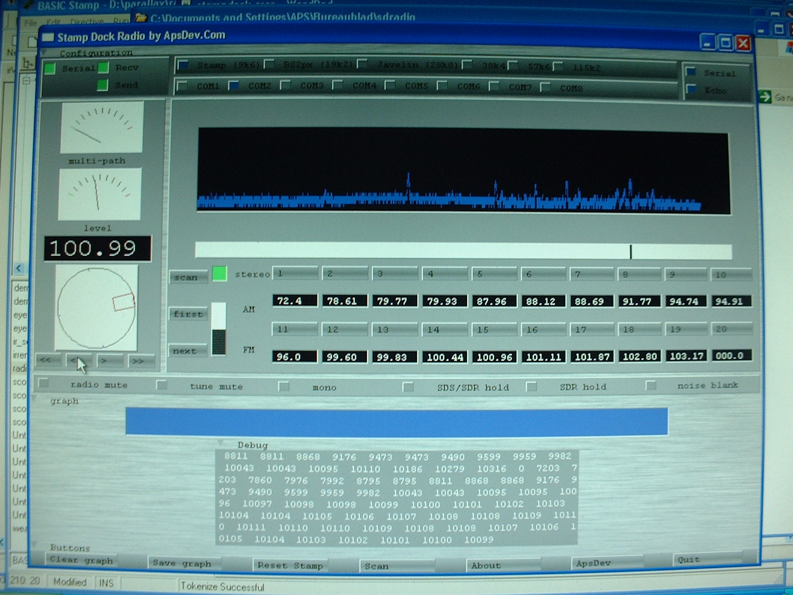
GUI:
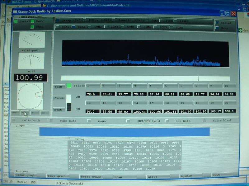
[ click to enlarge ] |
This is the first version of the GUI of the system in action.
If you press 'scan' it will draw a graph of the signal strengths found, also it will program
the 20 channel buttons with the found frequencies.
After that you can select channels by pointing the 'slider' to strong signals, or press a channel button
With the turnknob and the buttons below it you can fine tune the frequency.
To the left you see the current frequency and the signal level strenght.
|
|
Circuit:
[ click to enlarge ]
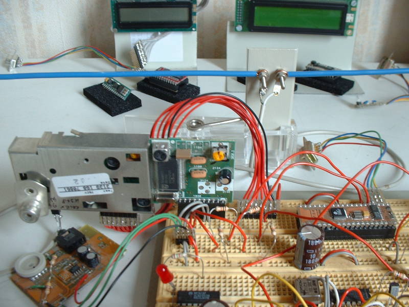
This is a picture of the hardware used to test.
It consists of a philips car radio tuner, a headphone amplifier and a BS2P.
Note that the headphone amplifier is a piece of circuit board from a CDrom drive.
The thick blue wires in the background are a small directional antenna i made for testing purposes.
|
|
|
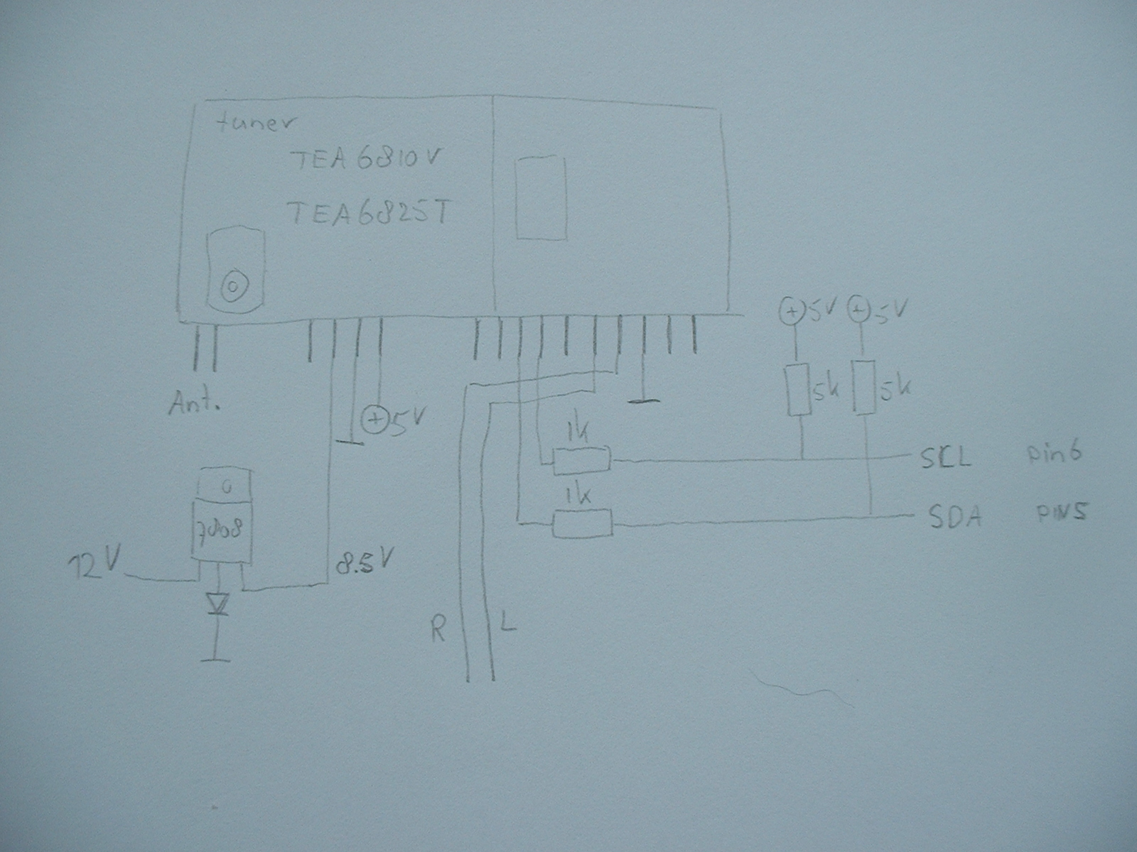
Pictures:
[ click to enlarge ] |
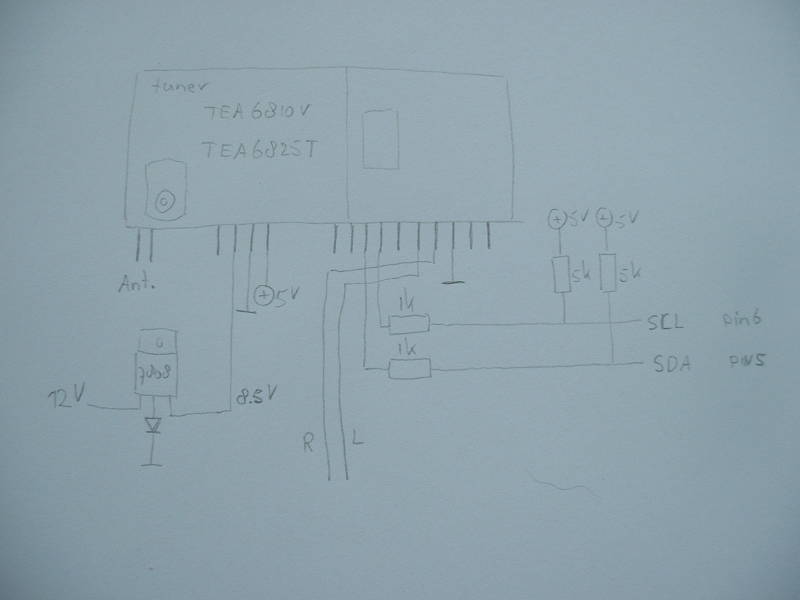
Circuit diagram in more detail.
Note that the tuner used needs 8.5 volts, which in this case was generated by putting a 1n4148 diode in
the ground connection of a 7808 voltage regulator. But you can also use a LM317 regulator to make 8.5volts.
|
|
[ advertisements ]
|
|
News:
|
|
Downloads:
Latest version:
Mirror1 12-sept-10 Download V1.0 6MB Stampdock radio.
Older versions:
Mirror1 12-sept-10 Download V1.0 6MB Stampdock radio.
|
|
Feedback:
StampDock Radio
Report a bug
|
|
Copyright 2008-2010 by Arend-Paul Spijkerman
|
|
|